 English
 Español
  Português
  русский
  Français
  日本語
日本語  Deutsch
  tiếng Việt
  Italiano
  Nederlands
  ภาษาไทย
  Polski
  한국어
한국어  Svenska
  magyar
  Malay
Malay  বাংলা ভাষার
  Dansk
Dansk  Suomi
Suomi  हिन्दी
  Pilipino
  Türkçe
  Gaeilge
  العربية
  Indonesia
  Norsk
Norsk  تمل
تمل  český
český  ελληνικά
  український
  Javanese
  فارسی
فارسی  தமிழ்
தமிழ்  తెలుగు
  नेपाली
  Burmese
  български
  ລາວ
ລາວ  Latine
  Қазақша
  Euskal
  Azərbaycan
  Slovenský jazyk
  Македонски
  Lietuvos
  Eesti Keel
  Română
  Slovenski
  मराठी
मराठी  Srpski језик


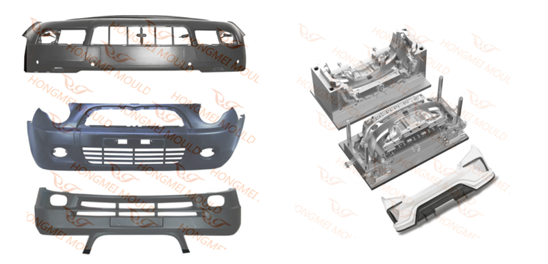
How to make a car front bumper mold
How to make a car front bumper mold?
1、 Structural analysis of plastic parts
The shape of the front bumper is similar to that of the saddle. The material is PP + epdm-t20, the shrinkage is 0.95%. PP is the main material of bumper and EPDM can improve the elasticity of bumper cover. T20 means adding 20% talcum powder to the material, which can improve the rigidity of bumper cover.
The features of plastic parts are:
(1) The shape is complex, the size is large, and the wall thickness is relatively small, which belongs to large-scale thin-walled plastic parts.
(2) The plastic parts have many bumps and penetrations, many stiffeners, and large flow resistance of injection molding melt.
(3) There are three buckles in the inner side of the plastic part, and it is very difficult to pull the core laterally at each place.
2、 Mold structure analysis
The front bumper main body injection mold adopts the inner parting surface, passes through the hot runner, and is controlled by the sequence valve. The inverted buckle on both sides adopts the structure of large inclined roof sleeve, horizontal inclined roof and straight roof, with the maximum dimension of 2500 × 1560 × 1790mm.
1. Design of forming parts
The advanced internal parting surface technology is adopted in the mold design, The utility model has the advantages that the parting clamp line is hidden on the non appearance surface of the bumper, which can not be seen after the assembly on the vehicle and will not affect the appearance. However, the difficulty and structure of this technology are more complex than that of the external type bumper, and the technical risk is also higher. The cost and price of the mold are also much higher than that of the external type bumper. However, due to the beautiful appearance, this technology is widely used in the middle and high-grade cars.
In addition, the plastic part has a large number of through holes, some of which are large in area. The air vent slot and void avoidance slot are designed at the place of collision, and the insertion angle is greater than 8 °, which can increase the service life of the mold, and is not easy to produce flash.
The front bumper injection mold parts and the template are made into a whole, and the template material can be pre hardened injection mold steel P20 or 718.
2. Design of gating system
The whole hot runner system is adopted in the pouring system of the mould, which has the advantages of convenient assembly and disassembly, low requirements for processing accuracy, no risk of glue leakage, reliable assembly accuracy, and no need for repeated disassembly and assembly in the future, as well as low maintenance and repair costs.
The front bumper is an appearance part, and the surface is not allowed to have fusion marks. When injection molding, the fusion marks must be rushed to the non appearance surface or eliminated, which is one of the key and difficult points in the mold design. The mold adopts the 8-point sequence valve hot runner gate control technology, namely SVG Technology, which is another advanced technology adopted by the mold. It controls the opening and closing of eight hot nozzles through the cylinder drive, so as to achieve the ideal effect of no weld mark on the surface of plastic parts.
Svg technology is a new hot runner forming technology developed in recent years to meet the needs of automobile industry for large-scale flat plastic parts and electronic industry for micro thin-walled parts. Compared with the traditional hot runner gate technology, it has the following advantages:
① The melt flow is stable, the holding pressure is more uniform, the feeding effect is significant, the shrinkage rate of plastic parts is consistent, and the dimensional accuracy is improved;
② It can eliminate the weld mark, or form the weld mark on the non appearance surface;
③ reduce the mold locking pressure and the residual stress of the plastic part;
④ reduce the molding cycle, and improve the mold labor productivity.
The simulation data chart of hot runner sequence valve was used in the front bumper. It can be seen from the mold flow analysis that under the normal injection pressure, mold locking force and mold temperature, the melt flow is stable and the quality of the plastic parts is good, so the service life of the mold and the product qualification rate can be fully guaranteed.
3. Design of side core pulling mechanism
As the front bumper adopts the parting surface of internal parting, the parting line at the back buckle of the fixed mold a plate is located under the inclined top of the moving mold side. In order to avoid the risk of damage to the mold during the operation, the core pulling procedure must be strictly controlled during the opening of the mold, see the mold working process for details.
The mold adopts the complex structure of the inclined roof designed under the straight roof and the transverse inclined roof (i.e. compound inclined roof) designed inside the inclined roof. In order to pull the core smoothly, there should be enough space between the inclined roof and the straight roof, and the contact surface between the inclined roof and the straight roof should be designed with a slope of 3 ° – 5 °.
The cooling water channel shall be designed for the large inclined roof and large straight roof on both sides of the injection mold of the internal parting bumper. The side hole of the fixed mold of the internal parting bumper shall be designed with a fixed mold needle structure for core pulling.
Here we want to explain: the injection mold of the inner parting bumper and the general injection mold Different from that, the plastic part is not ejected by staying in the moving mold, but by relying on the pull hook in the process of opening. The side core pulling 43 of the fixed mold pops up during the process of opening, and the plastic part will follow the fixed mold for a certain distance.
4. Design of temperature control system
The temperature control system design of the front bumper main injection mold has a great influence on the molding cycle and product quality. The mold temperature control system adopts the form of “straight cooling water pipe + inclined cooling water pipe + cooling water well”.
The main design points of the cooling channel of the die are as follows:
① The structure of the moving die is more complex and the heat is more concentrated, so it is necessary to focus on cooling, but the cooling channel must be kept at least 8mm away from the push rod, straight top and inclined top holes.
② The distance between water channels is 50-60mm, and the distance between water channels and cavity surface is 20-25mm.
③ If the cooling water channel can make straight holes, do not make inclined holes. For inclined holes with a slope of less than 3 degrees, directly change them to straight holes.
④ The length of the cooling channel should not be too different to ensure that the mold temperature is roughly balanced.
5. Design of guidance and positioning system
The mold belongs to a large thin-wall injection mold. The design of the guiding and positioning system directly affects the accuracy of the plastic parts and the life of the mold. The mould adopts square guide pillar and 1 ° precise positioning guide positioning, in which four square guide pillars 80 × 60 × 700 (mm) are used at the moving die side, and four square guide pillars 180 × 80 × 580 (mm) are used between the moving and fixed dies.
In the aspect of parting surface positioning, two cone positioning structures (also known as inner die tube position) are adopted at both ends of the die, and the inclination angle of the cone is 5 °.
6. Design of demoulding system

Plastic parts are large thin-walled parts, and the demoulding must be stable and safe. The middle position of the die adopts straight top and ejector pin, the diameter of ejector pin is 12mm. Because the contact area is small and difficult to return, it is easy to cause the ejector pin to collide with the cavity surface of the fixed model, so the inner parting bumper should be designed as straight as possible, and the ejector pin should be used less.
Because of the large number of push pieces, the release force and the reset force of push pieces are large, so the release system uses two hydraulic cylinders as the power source. See Figure 7 for the location of the cylinder. The dimension L in the figure is the distance to be delayed, which is related to the size of the fixed die reverse buckle, generally 40-70mm.
Due to the uneven surface of the moving core, all the fixed ends of the thimble and the driver cylinder are designed with a stop structure.
3、 Working process of mould
Because the bumper injection mold adopts the internal parting technology, the reverse position parting line of plate a is located under the inclined top of the moving mold side. In order to avoid the risk of damage to the mold during operation, the working process of the mold is very strict. Next, the steps and precautions are discussed from the beginning of mold closing.
① Before closing the die, the ejector pin plate is 50 mm away from the die bottom plate, so as to ensure that the reverse part of a plate does not touch the transverse small inclined roof protruding from the large inclined roof, and ensure that a plate can smoothly complete the closing action by pressing the reset rod.
② Press the pusher plate and the inclined top back to the reset position.
③ Before opening the die, it is necessary to apply pressure to the ejector cylinder in advance to ensure that the whole ejector system and a plate can be opened synchronously. When opening the mold, the A-plate and the thimble plate shall be opened for 60mm at first, so as to ensure that the plastic part and the transverse small inclined roof are all separated from the reverse buckle surface of the A-plate.
④ The fixed mold a plate continues to open the mold, and the ejector pin plate in the moving mold remains unchanged in the ejection state of 60mm, so as to achieve the function of separating the a plate and the straight top.
⑤ After the fixed mold is opened to the required space, the ejector pin plate in the moving mold continues to be pushed out to 164mm. At this time, the horizontal small inclined top guide rod reaches the turning point of the change angle of the guide rail, and the plastic part reverse buckle surface is separated from the mold. If the plastic part is stuck with a small inclined roof at this time, directly pull the plastic part out of the mold by hand, otherwise, push the ejector plate to the final position of 210mm.
⑥ If the product slightly sticks to the small inclined roof, the ejection is completed when the product is pushed out to 164mm. Take down the product and directly cycle to step ① to prevent the product from being pulled back by the horizontal small inclined roof, so that the product cannot be taken down.
⑦ If the plastic part does not stick to the transverse small inclined roof, push the ejector pin plate to 210mm, remove the plastic part after demoulding, and cycle to step ①.
4、 Results and discussion
1. The mold adopts the inner parting technology to ensure the beautiful appearance of the plastic parts.
2. The second core pulling structure of “compound inclined roof” is adopted in the die, which solves the problem of lateral core pulling in the complex part of the plastic part.
3. The hot runner gating system of eight point needle valve sequence valve is adopted in the die, which solves the problem of melt filling of large-scale thin-wall plastic parts.
4. The hydraulic pressure is used as the power of the demoulding system to solve the problems of large demoulding force of plastic parts and difficult to reset push parts.
The practice shows that the die structure is advanced and reasonable, the size is accurate, and it is a classic work of automobile die. Since the mold was put into production, the lateral core pulling action has been coordinated and reliable, and the quality of plastic parts has been stable, meeting the requirements of customers.
Contact me

Previous:Multi Cavity Plastic Hanger Mold
Send Inquiry


X
We use cookies to offer you a better browsing experience, analyze site traffic and personalize content. By using this site, you agree to our use of cookies.
Privacy Policy